Chapter 1
The vapour compression cycle
Heat flows naturally from hot to cold. A refrigerator makes it flow the other way by using a fluid that boils at a low temperature. The refrigerant boils in the evaporator, taking heat from the space being cooled. The compressor raises its pressure, and with it the temperature at which it will condense. In the condenser it gives that heat to the room air. The expansion device drops the pressure again so the liquid can boil once more.
1 → 2 Compression
The hermetic compressor draws in slightly superheated vapour from the evaporator and compresses it. Pressure and temperature rise; the discharge line is hot to touch. The work input W is measured by the energy meter.
2 → 3 Condensation
The air-cooled condenser first removes the superheat, then the latent heat, and the vapour condenses to liquid at constant pressure. The heat rejected is Qc = Qe + W.
3 → 4 Expansion
The liquid passes the filter-drier and is throttled through a capillary tube or thermostatic expansion valve. No work is done and almost no heat exchanged, so enthalpy stays the same while the pressure, and the boiling point, fall.
4 → 1 Evaporation
The cold liquid–vapour mix boils in the evaporator coil, taking heat Qe from the water, brine or air around it. This is the useful effect. The vapour leaves a few degrees superheated and returns to the compressor.
What is on the panel
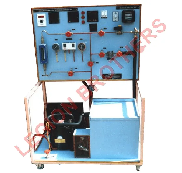
- Pressure and compound gauges
- Discharge and suction pressures. They read gauge pressure; add atmospheric (about 1.01 bar) before using property tables.
- Thermocouples
- K-type sensors at compressor inlet and outlet, condenser outlet and evaporator inlet, plus the water, brine or air being cooled.
- Energy meter
- Electrical input to the compressor. Count disc revolutions or LED pulses over a timed period.
- Rotameter
- Volume flow of liquid refrigerant in the liquid line, used to find the refrigerant mass flow.
- LP/HP cutout
- Stops the compressor if suction pressure falls too low or discharge pressure rises too high.
- Solenoid valve and filter-drier
- The solenoid closes the liquid line when the unit stops; the drier removes moisture and dirt that would block the capillary.
Which rig teaches what
Chapter 2
Reading the p-h chart
Plot pressure (on a log scale) against enthalpy and the whole cycle becomes a simple shape. Inside the dome the refrigerant is a liquid–vapour mix; to the left it is liquid, to the right vapour. Evaporation and condensation are horizontal lines, throttling is vertical, and compression slopes up to the right. Enthalpy differences read straight off the chart give every energy flow per kilogram of refrigerant.
Properties of R-134a; 5 K suction superheat and isentropic (ideal) compression. Older rigs used R-12 or R-22: the method is the same, only the numbers change. Check the refrigerant on your rig's nameplate.
- Pressures (absolute)
- 2.43 bar → 10.17 bar · ratio 4.2
- Enthalpies h₁, h₂, h₃ = h₄
- 400, 431, 256 kJ/kg
- Refrigerating effect h₁ − h₄
- 143.6 kJ/kg
- Compressor work h₂ − h₁
- 30.6 kJ/kg · discharge 50 °C
- COP = (h₁ − h₄) ÷ (h₂ − h₁)
- 4.70
- Carnot COP = Te ÷ (Tc − Te)
- 5.96
Two things to try. Lower the evaporating temperature: the pressure ratio climbs, the compressor does more work per kilogram and the COP falls. That is why a freezer costs more to run than a fridge. Then add subcooling: point 3 moves left, so point 4 does too, and each kilogram absorbs more heat for the same work.
Chapter 3
Measuring COP on the rig
On the vapour compression rig (RACC04) the cycle comes from the gauges. Convert each gauge reading to absolute pressure and look up its saturation temperature: that gives the evaporating and condensing temperatures. The rotameter in the liquid line gives the refrigerant flow, so the refrigerating capacity is ṁ × (h₁ − h₄). The energy meter gives the electrical input.
Energy meter: P (kW) = n × 3600 ÷ (EMC × t), where n is the number of revolutions or pulses counted in t seconds and EMC is the meter constant printed on it (rev/kWh or imp/kWh).
Your readings
Cycle temperatures
Saturation at gauge + 1.01 bar
-4.1 / 43.0 °C
Refrigerating capacity
ṁ = 22.7 kg/h; Q = ṁ (h₁ − h₄) = 0.25 TR
0.88 kW
Compressor input
From the energy meter
0.40 kW
Actual COP
Theoretical 4.42; relative COP 50 %
2.19
The actual COP is always lower than the ideal one. The compressor is not isentropic, the motor has losses, pressure drops in the pipes and valves, and the evaporator and suction line pick up heat from the room. A relative COP of 40–60 % is normal for a small hermetic unit. If the evaporator sits in a vessel of water, you can cross-check the capacity from the water side: Q = m cp ΔT ÷ t.
Chapter 4
The ice plant
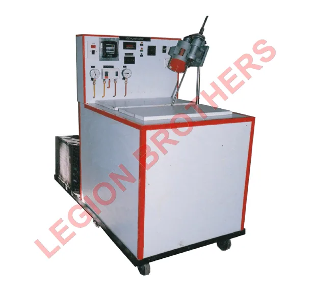
In the ice plant (RACC01) the evaporator coil sits in a tank of brine: water with salt, so it stays liquid well below 0 °C. A stirrer keeps the brine moving around galvanised iron cans of water. The brine is held at about −5 to −10 °C, and the water in the cans gives up three amounts of heat to become ice:
q = cp,water (Tw − 0) + 335 + cp,ice (0 − Tice) kJ per kg of ice
Your readings
Heat per kg of ice
Sensible + latent + subcooling of the ice
471 kJ/kg
Useful refrigeration
Total 1178 kJ over the batch
0.055 kW
Ice output
At this batch time, running all day
10.0 kg/day
Plant COP
Useful refrigeration ÷ electrical input
0.16
The plant COP comes out far below the cycle COP from Chapter 2, and that is the lesson of this experiment. Only the heat taken out of the water counts as useful. The compressor also has to pull down the brine, tank and cans, absorb heat leaking in through the insulation and remove the heat from the stirrer motor. Better insulation, a lid on the tank and a smaller stirrer all raise the plant COP without changing the refrigeration circuit.
Chapter 5
Air conditioning and psychrometry
An air conditioner controls humidity as well as temperature. Psychrometry is the study of moist air. Two thermometers do the work: the dry bulb reads the air temperature, and the wet bulb has a wet wick and reads lower because water evaporates from it. The drier the air, the bigger the difference. From the two readings you get the humidity ratio W (kg of water per kg of dry air), relative humidity, enthalpy and dew point.
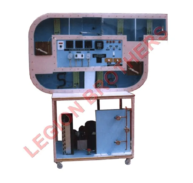
When air crosses a coil colder than its dew point, it is cooled and moisture condenses out: cooling and dehumidification. The total heat removed splits into a sensible part (temperature) and a latent part (moisture). The sensible heat factor SHF = sensible ÷ total tells you which one dominates. The re-circulating trainer (RACC02) adds a heater and a steam humidifier, so you can also run heating and humidification and plot each process on the chart. The window AC trainer (RACC05) does the same job in a packaged unit, with the evaporator facing the room and the condenser outdoors.
Your readings
Sea-level pressure. Air flow = duct velocity × duct area.
- Before coil (A)
- 50 % RH · W 13.3 g/kg · h 64.1 kJ/kg
- After coil (B)
- 82 % RH · W 10.5 g/kg · h 44.7 kJ/kg
- Cooling load
- 3.68 kW (1.05 TR) = 2.35 sensible + 1.33 latent
- Sensible heat factor
- 0.64
- Condensate
- 1.88 kg/h
- COP
- 2.63
The wet bulb cannot be higher than the dry bulb. Check the readings.
Collect the condensate in a measuring jar during the run and compare it with the calculated value: it is a good check that the wet-bulb wicks were properly wetted.
Chapter 6
Vapour absorption
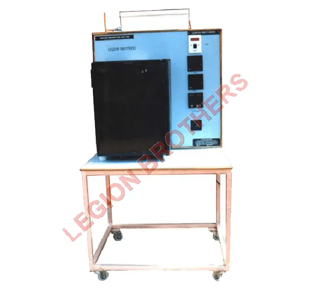
An absorption refrigerator replaces the compressor with heat. The rig (RACC03) uses an Electrolux-type sealed unit, like a small household or hotel-room refrigerator, with three fluids:
Ammonia
The refrigerant. It evaporates in the evaporator, taking heat from the cold space, just as in a compression system.
Water
The absorbent. In the absorber it soaks up the ammonia vapour; in the generator, an electric heater boils the ammonia out again.
Hydrogen
Keeps the total pressure the same everywhere. Ammonia evaporates into the hydrogen at its own low partial pressure, so no pump or valve is needed.
Because the unit is sealed, the ammonia pressure and flow cannot be measured. Instead, measure the heat taken from water flowing through the evaporator coil (measuring jar and stopwatch, inlet and outlet temperatures), and the heater input from the voltmeter and ammeter.
Your readings
For the ideal COP
Refrigerating effect
Q = ṁ cp (Tin − Tout)
27.9 W
Heat input
V × I at the generator heater
138 W
Actual COP
Q ÷ heat input
0.20
Ideal COP
(1 − Ta/Tg) × Te ÷ (Ta − Te), in kelvin
2.15
Absorption COP is low, typically 0.1–0.3 for a small diffusion unit, against 2–3 for a compression system. Its strengths are elsewhere: no moving parts, silent running, and it can run on waste heat, gas or solar heat instead of electricity.
Chapter 7
Refrigerants and safe operation
Refrigerants are chosen for their boiling point, pressure, efficiency and safety, and now for their effect on the environment. ODP is ozone depletion potential (R-11 = 1); GWP is the 100-year global warming potential relative to CO₂.
| Refrigerant | Type | Boils at 1 atm | ODP | GWP | Status |
|---|---|---|---|---|---|
| R-12 | CFC | −30 °C | 1 | 10 900 | Phased out under the Montreal Protocol |
| R-22 | HCFC | −41 °C | 0.055 | 1 810 | Being phased out |
| R-134a | HFC | −26 °C | 0 | 1 430 | Common in teaching rigs and car AC; HFCs being phased down |
| R-600a (isobutane) | HC | −12 °C | 0 | 3 | Domestic refrigerators; flammable |
| R-290 (propane) | HC | −42 °C | 0 | 3 | Room AC; flammable |
Running the rig safely
- Check that all hand valves in the circuit are open before starting. Never run the compressor against a closed discharge valve.
- Let the condenser fan run whenever the compressor runs. A blocked condenser drives the discharge pressure up until the HP cutout trips.
- If a cutout trips, find the cause before resetting it. Wait a few minutes before restarting so pressures can equalise.
- Wait for steady state (stable pressures and temperatures, usually 15–30 minutes) before recording readings.
- The discharge line and compressor shell are hot; the suction line and evaporator can cause cold burns.
- Leave charging, evacuation and leak repair to a trained technician. Refrigerant must be recovered, never vented.
Chapter 8
Test your knowledge
-
In the vapour compression cycle, where does the refrigerant absorb heat from the space being cooled?
Evaporator. The refrigerant boils at low pressure and temperature in the evaporator, taking its latent heat from the surroundings.
-
Which process happens at (nearly) constant enthalpy?
Throttling in the expansion device. Throttling does no work and exchanges almost no heat, so h4 = h3: a vertical line on the p-h chart.
-
The compound gauge on the suction line reads 1.5 bar. What pressure goes into the property table?
2.5 bar absolute (gauge + atmospheric). Gauges read above atmospheric pressure; property tables use absolute pressure, so add about 1.01 bar.
-
Lowering the evaporating temperature with the same condensing temperature will…
Lower the COP. The compressor must lift the vapour through a bigger pressure ratio, so work per kg rises and the refrigerating effect falls.
-
Subcooling the liquid leaving the condenser…
Increases the refrigerating effect. A lower h3 means a lower h4, so each kilogram can absorb more heat in the evaporator for the same compressor work.
-
One ton of refrigeration (TR) is about…
3.5 kW. 1 TR = 3.517 kW, roughly the rate needed to freeze a short ton of water at 0 °C in 24 hours.
-
Why is the ice plant's measured COP far lower than the cycle COP?
Brine, tank and cans must be cooled and heat leaks in, as well as the stirrer's work. Only the heat taken from the water counts as useful; everything else the refrigerant removes is a loss.
-
Air leaves a cooling coil colder and with a lower humidity ratio. The process is…
Cooling and dehumidification. The coil is below the air's dew point, so moisture condenses as the air cools: both sensible and latent heat are removed.
-
In the Electrolux-type absorption refrigerator, what drives the cycle instead of a compressor?
Heat supplied to the generator. The heater boils ammonia out of the water solution; hydrogen equalises the pressure so no mechanical pump is needed.
-
Which refrigerant has zero ozone depletion potential?
R-134a. R-134a contains no chlorine. R-12 (a CFC) and R-22 (an HCFC) damage the ozone layer and are phased out under the Montreal Protocol.
Answers
- Evaporator
- Throttling in the expansion device
- 2.5 bar absolute (gauge + atmospheric)
- Lower the COP
- Increases the refrigerating effect
- 3.5 kW
- Brine, tank and cans must be cooled and heat leaks in, as well as the stirrer's work
- Cooling and dehumidification
- Heat supplied to the generator
- R-134a