Chapter 1
Two ways to turn heat into work
Every turbine does the same basic job: it lets a hot, high-pressure fluid expand, speeds it up through nozzles, and catches its momentum on blades fixed to a rotating shaft. The two rigs in this programme use different fluids and different cycles.
| Steam power plant (MSTC01) | Gas turbine (AGTC01) | |
|---|---|---|
| Working fluid | Water and steam, recirculated | Air and combustion gas, once through |
| Cycle | Rankine | Brayton (open cycle) |
| Heat added | Outside the fluid, in a diesel-fired boiler | Inside the fluid, by burning kerosene in the combustor |
| Useful output | Shaft power to a DC generator | Thrust from the exhaust jet |
| Key measurements | Pressures, temperatures, steam and cooling-water flow, generator volts and amps | Thrust, speed, air and fuel flow, pressures, exhaust temperature |
Steam power
Gas turbine
Chapter 2
The steam power plant
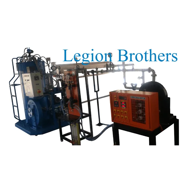
The mini power plant (MSTC01) has all four parts of a thermal power station on one base frame: a boiler, a turbine, a condenser and a feed pump. The same water goes round and round, changing between liquid and steam.
4 → 1 Boiler
A diesel burner heats the feed water at constant pressure: first to boiling point, then into dry saturated steam. The boiler on the rig works up to about 10 bar. Softened feed water keeps scale off the tubes.
1 → 2 Turbine
Steam expands through a nozzle into a high-speed jet that drives the blades of a single-stage wheel. The wheel is belt-coupled to a DC generator, loaded by a bank of lamps.
2 → 3 Condenser
Exhaust steam condenses on the tubes of a shell-and-tube condenser cooled by water, measured on a rotameter. The heat given to the cooling water is the biggest loss in any steam plant.
3 → 4 Feed pump
The pump returns the condensate to boiler pressure. Pumping a liquid takes very little work compared with what the turbine produces.
Chapter 3
The Rankine cycle
The steam plant follows the Rankine cycle. On a temperature–entropy (T-s) chart the area inside the cycle is the net work. Heat goes in along the top: warming the water, boiling it at constant temperature, and superheating it if the plant has a superheater. Heat leaves along the bottom, in the condenser. Expansion in an ideal turbine is a vertical line.
Water and steam properties from IAPWS-IF97 (CoolProp). Ideal turbine and pump; pressures absolute.
- Turbine inlet
- 180 °C · h₁ 2777 kJ/kg
- Turbine work h₁ − h₂
- 391 kJ/kg · pump 0.9 kJ/kg
- Exhaust dryness x₂
- 0.872
- Cycle efficiency
- 16.5 % (Carnot 17.7 %)
- Steam rate
- 9.2 kg/kWh
- Work ratio
- 0.998
Three things to try. Lower the condenser pressure: the condensing temperature falls and efficiency climbs, which is why power stations run their condensers under vacuum. Raise the boiler pressure: efficiency rises, but the exhaust gets wetter, and water droplets erode turbine blades. Add superheat: efficiency rises and the exhaust dries out. Notice how small the pump work is; the work ratio stays close to 1.
Chapter 4
Testing the boiler
Boiler efficiency is the heat that ends up in the steam divided by the heat in the fuel. Measure the feed-water flow (equal to the steam flow at steady water level), the steam pressure, the feed-water temperature and the fuel used over a timed run.
η = ṁs (hg − hfeed) ÷ (ṁf × CV), and equivalent evaporation = ṁs (hg − hfeed) ÷ 2257
Your readings
Dry saturated steam assumed.
Heat to each kg of steam
hg = 2781 kJ/kg minus the feed water's heat
2655 kJ/kg
Heat output
Into the steam
243 kW
Boiler efficiency
Steam heat ÷ fuel heat
85.5 %
Equivalent evaporation
From and at 100 °C; factor 1.176
388 kg/h
Boilers are often rated "from and at 100 °C": the heat it would take to evaporate that much water already at 100 °C, at atmospheric pressure. Real feed water is colder and the steam is at higher pressure, so each kilogram needs more heat and the actual steam output is lower than the rating. Compare boilers on equivalent evaporation; report your own plant on actual output. Where does the rest of the fuel's heat go? Mostly up the flue in hot gases, plus radiation from the shell and blowdown.
Chapter 5
The impulse steam turbine
The rig's turbine is a single-stage, single-row impulse wheel fed by one nozzle, the simplest design there is. The whole pressure drop happens in the nozzle, which turns it into a jet moving at hundreds of metres per second: c₁ = φ √(2 Δhs). The curved blades turn the jet round and the change in its momentum pushes the wheel.
How much of the jet's energy the blades catch depends on the speed ratio σ = blade speed ÷ jet speed. With nozzle angle α and blade friction factor k, the blade efficiency is ηb = 2σ (cos α − σ)(1 + k), highest when σ = cos α ÷ 2.
- Jet speed c₁
- 740 m/s
- Speed ratio σ
- 0.20 (best 0.47)
- Blade efficiency
- 55 % (maximum 82 %)
To reach the best ratio from a 700 m/s jet the blades would need to move at over 300 m/s, too fast for a small wheel. Large turbines solve this with compounding: several rows of blades (Curtis, velocity compounding) or several nozzle-and-wheel stages (Rateau, pressure compounding), each taking a share of the drop. A small single-stage turbine runs well below its best speed ratio, so expect a low efficiency from the test below.
Turbine performance test
Hold the inlet pressure steady and switch on lamps to load the generator, step by step. At each load record the steam flow (collect the condensate over a timed period) and the generator volts and amps. Plot steam flow against electrical output: the points fall close to a straight line, the Willans line. Its intercept is the steam needed just to spin the turbine with no load.
Your readings
Dry saturated steam at the inlet.
Isentropic drop
Ideal exhaust dryness 0.901
303 kJ/kg
Power
Ideal ṁ Δhs = 3.37 kW; electrical V × I
0.42 kW
Turbine efficiency
Shaft 0.52 kW ÷ ideal power
15.6 %
Specific steam consumption
Steam flow ÷ electrical output
95 kg/kWh
Chapter 6
The gas turbine and Brayton cycle
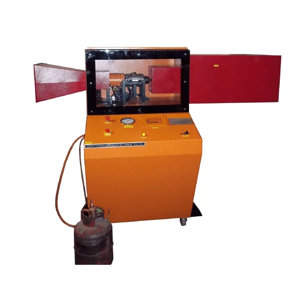
The aeronautical gas turbine (AGTC01) is a small turbojet. Air is drawn in and squeezed by a centrifugal compressor, fuel is sprayed into it and burned in the combustor, and the hot gas expands through an axial turbine. The turbine takes just enough work to drive the compressor. The gas that leaves it is still hot and above atmospheric pressure, so it accelerates through the nozzle into a jet, and the reaction is thrust.
Ideally the cycle is the Brayton cycle: isentropic compression, constant-pressure heating, isentropic expansion. Its efficiency depends on the pressure ratio r: η = 1 − r−(γ−1)/γ. In a real engine, compressor and turbine losses and the turbine entry temperature (TIT) matter just as much.
Air-standard model: cold air (cp 1.005, γ 1.4) through the compressor, hot gas (cp 1.148, γ 1.333) after the combustor; 5 % pressure loss in the combustor; static test.
- Temperatures
- compressor out 174 °C · turbine out 726 °C · jet 639 °C
- Air–fuel ratio
- 49 : 1
- Jet velocity
- 448 m/s
- Specific thrust
- 457 N per kg/s of air
- TSFC
- 45 g/kN·s
- Thermal efficiency
- 11.6 % (ideal Brayton 25.5 %)
The turbine cannot drive the compressor at these settings, so there is no pressure left for the jet. Raise the turbine entry temperature or the component efficiencies.
Points 1–5 are intake, compressor exit, turbine entry, turbine exit and jet. Try lowering the compressor efficiency: the turbine must take more work, less is left for the jet, and below a certain point the engine cannot sustain itself. This is why small engines need a high turbine entry temperature, and why their exhaust runs at 600 °C or more.
Chapter 7
Testing the gas turbine, safely
The engine sits on a load cell that measures thrust directly. The software logs speed, pressures, temperatures, air flow (from the pressure drop across the intake) and fuel flow. In a static test the jet velocity follows from thrust and mass flow: F = (ṁa + ṁf) Vj.
Your readings
Thrust
kg × 9.81
19.6 N
Jet velocity
Air–fuel ratio 35 : 1
273 m/s
TSFC
Fuel 2.00 g/s ÷ thrust
102 g/kN·s
Thermal efficiency
Jet power 2.67 kW ÷ fuel power 86 kW
3.1 %
Repeat at several throttle settings and plot thrust, TSFC and exhaust temperature against speed. Compare the measured thrust with the cycle calculation in Chapter 6: the gap shows the losses the simple model leaves out, such as intake and nozzle losses, heat lost through the casing and incomplete combustion. Small engines are much less efficient than large ones: tip clearances and friction are a bigger share of a tiny compressor.
Steam plant safety
- Steam boilers above 22.75 litres must be registered under the Indian Boilers Act and inspected; keep the certificate current.
- Check the water level gauge, safety valve and low-water cut-off before every firing.
- Use softened feed water and blow down as the manual specifies.
- Open the turbine drain and warm the steam line before admitting full steam.
- Steam pipes and the turbine casing are hot enough to burn; keep lagging in place.
Gas turbine safety
- Wear ear protection; the engine is very loud at full speed.
- Never stand in line with the rotor or behind the exhaust jet.
- Keep a CO₂ fire extinguisher at the rig and no loose items near the intake.
- Run outdoors or with the exhaust ducted outside.
- Follow the start and cool-down sequence; do not shut the fuel while the exhaust is still above its limit.
Chapter 8
Test your knowledge
-
In the steam power plant, where is the steam's heat energy turned into shaft work?
Turbine. The nozzles turn the pressure drop into a high-speed jet, and the blades turn the jet's momentum into torque.
-
Why does the plant need a condenser?
To recover water and lower the turbine exhaust pressure. Condensing the exhaust lets the cycle reuse treated water, and a lower exhaust pressure means a bigger enthalpy drop across the turbine.
-
Raising the boiler pressure, with the same condenser pressure, generally…
Raises cycle efficiency but makes the exhaust wetter. Heat is added at a higher average temperature, but expansion from a higher pressure ends further inside the dome.
-
A boiler rated '400 kg/h from and at 100 °C' means…
It can supply heat equal to evaporating 400 kg/h of water already at 100 °C. Equivalent evaporation is a common rating basis. Real output is lower when feed water is colder and steam pressure higher.
-
In a single-stage impulse turbine, the pressure drop happens…
Only in the nozzle. In pure impulse blading the whole drop is in the nozzle; the blades only change the jet's direction at constant pressure.
-
For maximum blade efficiency, the blade speed should be about…
Half the steam speed × cos α. Optimum σ = u/c₁ = cos α ÷ 2. Small turbines usually run well below it, which is why their efficiency is low.
-
In the turbojet, what does the turbine drive?
The compressor (and accessories). The turbine takes just enough work to drive the compressor; the remaining energy accelerates the gas through the nozzle as thrust.
-
Ideal Brayton cycle efficiency depends mainly on…
Pressure ratio. η = 1 − r^−(γ−1)/γ. In a real engine, turbine entry temperature and component efficiencies matter too.
-
Thrust-specific fuel consumption (TSFC) is…
Fuel flow ÷ thrust. Lower TSFC means less fuel for the same thrust. Small engines have much higher TSFC than airliner turbofans.
-
Under the Indian Boilers Act, a boiler like the one on the steam plant must…
Be registered and periodically inspected. Steam boilers above 22.75 litres capacity must be registered and carry a valid certificate from the boiler inspectorate.
Answers
- Turbine
- To recover water and lower the turbine exhaust pressure
- Raises cycle efficiency but makes the exhaust wetter
- It can supply heat equal to evaporating 400 kg/h of water already at 100 °C
- Only in the nozzle
- Half the steam speed × cos α
- The compressor (and accessories)
- Pressure ratio
- Fuel flow ÷ thrust
- Be registered and periodically inspected